The definition of steel structure
When it comes to building types, choosing the most future-proof type beforehand is the obvious choice. As such, steel structure is the type of building you’re looking for, performing better than any other possible structure type – concrete, timber, and so on.
Steel itself is an alloy of two material types – carbon and iron. Steel can also be infused with special properties by adding a number of additional materials in small percentages, be it sulfur, chrome, nickel, phosphorus, manganese, etc. This allows for several different varieties of steel to be produced. For example:
- Adding copper allows for better corrosion resistance properties of steel;
- Higher yield strength and tensile strength can be achieved by adding manganese and carbon, although there are two downsides, as well – the end result is harder to weld and has lower ductility (metal’s capability of extending by drawing without fractures);
- Both corrosion resistance and high-temperature resistance can also be boosted by adding nickel and chrome;
- Fatigue strength and the ability to weld can be improved by adding sulfur and phosphorus to the mix.
By its nature, steel structure is a structure made of multiple components connected with each other – with each component being created out of structural steel. Structural steel, on the other hand, is a steel-based construction material fabricated in a specific shape and composition to fit the necessary specifications.
There’s a massive selection of different steel sections that can be used as parts of a steel structure, with different shapes, sizes, and more. Some of the more common shapes that are used as steel structure materials are:
- Angle – a cross-section shaped like a letter “L”
- Sheet – a thin, flat piece of metal, usually 6 mm thick or less
- Plate – a thicker variation of a sheet, thicker than one-fourth of an inch
- HSS/SHS – Hollow Structural Section, or Structural Hollow Section, is a shape that includes circular, rectangular, elliptical, and square sections
- I-beam – a cross-section shaped like a letter “I”; a wide term that includes different kinds of beam types depending on the country:
- In Europe – a wide variety of sections, such as HL, IPE, HD, HE, and so on
- In the US – H sections, W-shapes, etc.
- In Britain – mainly UCs and UBs (Universal Columns and Universal Beams)
- Structural channel – C cross-sections/C-beams
- Rod – a long and relatively thin steel piece
- Z-shape – half a flange in different directions, closely resembles letter “Z” with its composure
- Tee – a cross-section shaped like a letter “T”
- Rail profile – a variation of I-beam that is asymmetrical in its nature, includes at least four different variations:
- Vignoles rail
- Grooved rail
- Railway rail
- Flanged T-rail
While some of these variations are made by welding together either bent or flat plates, the majority of the examples above are created with either hot or cold rolling – passing metal stock through pairs of rolls to make them less thick.
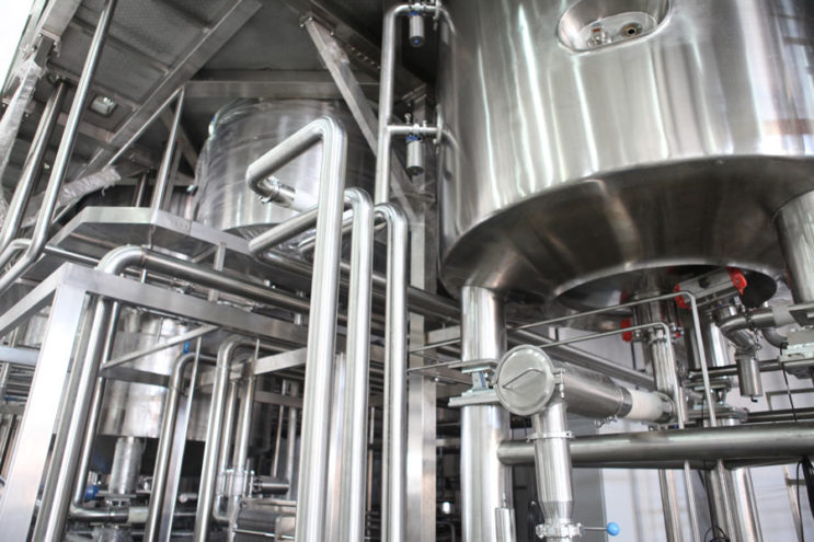
When built right, this structure is supposed to provide fully rigid contraception capable of supporting massive weights. Some of the building types that are using steel structures right now are bridges, towers, pipe racks, high-rise buildings, industrial buildings, infrastructure elements, and more.
Benefits and disadvantages
As with any other type of building, steel structure constructions have their own problems and benefits. Starting with the positive, steel structures’ advantages are quite numerous:
- Steel structures have all of the advantages of both mass production and prefabrication, with a few exceptions;
- Strengthening steel structures at any point in the future is a possibility, which works towards a prolonged lifecycle;
- Ductility – a property of steel to undergo plastic deformation before failing completely, improving reserve strength;
- Great fatigue strength;
- The overall speed of construction when using steel structures is impressively high, which allows for decreasing the spendings that you’ll usually have with prolonged construction jobs;
- Steel, in general, has an impressive strength-to-weight ratio, which makes structures themselves to be relatively light in comparison with the amount of weight they can hold;
- A lot of steel properties can be predicted with relatively high accuracy, making it far easier to calculate potential stress levels and other important criteria.
Of course, there would not be a market of multiple choices if one was a perfect fit for everything. As such, steel structures also have their own potential disadvantages, such as:
- Fireproofing steel structures is a necessity since intense heat is capable of drastically decreasing the overall strength of steel;
- Corrosion is also a massive factor when it comes to steel, in general, and steel structures are not exempt from this rule – especially when it comes to exposing such structures to water and air (bridges, mostly), hence regular maintenance and corrosion treatment is needed;
- Steel structures are often more expensive than other structure types, which makes them a far less attractive choice for smaller projects with a limited budget.
Detailed steel structure construction process
Every steel building’s construction process begins with creating a baseline for the building in question. This baseline is referred to as the steel frame structure, and there are four main parts to this process – foundation construction, column construction, steel beam erection, and floor system generation.
Foundation
The creation of a foundation is the first part of creating a steel frame for your project, the very first step in the steel structure construction process. There are several different types of foundations that can be used in the steel construction process, and the biggest deciding factor towards a specific foundation type is the soil-bearing capacity.
To figure out what type of foundation needs to be used for a specific structure type, a process called soil investigation is performed – it evaluates the soil condition in the same location when the steel structure is planned to be built by investigating both surface and subsurface levels of the aforementioned soil.
The overall final load of the steel structure construction also influences the choice of foundation type quite a lot. For example, if the soil investigation process has shown that the overall soil strength is rather poor, and the planned steel structure load is estimated as high, then it is recommended to use a pile foundation. This is a specific foundation type that lets the steel structure transfer its load down to the level of stiff soil.
Alternatively, if the expected steel structure load ranges from low to moderate, then it is possible to use either the strip foundation or the reinforced concrete-bearing pads since both of these foundation types transfer their load directly to the soil below with the expectation that it can support the load it receives from the foundation.
Columns
Column installation is the second step in the steel construction process after the foundation installation. This particular step can also vary quite a lot depending on the total structure load of the future steel building. Different structure load has a direct correlation with different steel column sizes – with steel columns being produced well before the construction process begins.
There are two important parts to this particular segment – the connection between the foundation and the columns, as well as the connection (splices) between the columns themselves. When it comes to connecting the foundation and the columns, welding is used to connect column ends with base plates. Base plates themselves can have different shapes, but the most useful ones are rectangular or square since those are usually the easiest to work with because the spacing between bolts is the highest for these base plate shapes.
Splices, on the other hand, are rather basic connections between different steel columns that are performed every two or three storeys of a building. This allows for columns to be rather long, but not long enough to be problematic in terms of production and delivery. Splices are usually made about 0.6 meters above the current floor, and welding is used to join two steel columns together when the columns themselves are circular in shape.
Beams
Steel beam erection is the next logical step in this steel structure construction process, used mainly to transfer loads from different floors (as well as a roof) to previously mentioned columns. There are many different shapes and sizes that a beam can take, with the longest ones being up to 18 meters, while the most commonly used beams are usually from 3 to 9 meters.
There are also two groups of connections that can be considered when it comes to erecting steel beams. The first group of connections details how beams are connected to the existing columns – separated into two more groups depending on the load types that the joint in question is going to be influenced by. If the expected loads are purely vertical, then the best option is to use simple connections, such as double angle, fin plate, or flexible end plate. If the expected load is both vertical and torsion, then it is recommended to use different types of connections, such as extended end plates or full-depth end plates.
As for the connection between beams themselves, the primary method here is to use end plate beam-to-beam connection. There is also the factor of leveling secondary beams to match their height with primary beams (since secondary beams support the floor system by default) – this can be achieved by either notching a part of the secondary beam or by welding a projected bracket to the primary beam so that there is no need for secondary beam modification during the beam-to-beam connection process.

Floor system
The installation of a floor system is the last piece of this puzzle that is steel construction, and there are quite a lot of different types of floor systems that can be utilized in the steel construction process. Floors are usually installed at the same time or after beams are erected, and floors tend to act both as a “diaphragm” of sorts for the structure, as well as a supporting structure for vertically applied loads. Different variations of floor systems include:
- Non-composite beams with precast concrete units;
- Long-span composite beams and slabs with the addition of metal decking;
- Cellular composite beams and slabs with the addition of steel decking;
- Short-span composite beams and slabs with the addition of metal decking;
- Composite beams with precast concrete elements;
- Slimflor beams with precast concrete elements;
- Slimdek floor systems.
Steel bracing and cladding are also often addressed in the context of this topic. Bracing is used to transfer lateral force from the structure itself to the columns and then to a foundation. Cladding, on the other hand, is used to protect the inside area of the steel frame structure and may take the form of either sheet cladding or brick cladding.
Types of steel structures in the form of buildings
There are many different examples of steel structures that we’ve provided above – and all of them can be split into four main types of structures. Each of these structures has its own approach to building and only works for specific types of steel structure constructions. As such, these four steel structure design types are:
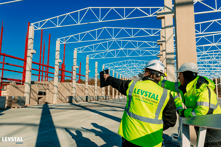
- Portal frame. The most common type of light steel structure, a portal frame is a widely popular type of steel structure that relies only on section steel, steel pipes, and C/Z steel to withstand the force of the entire structure. It is often used for many different building types, be it industrial, agricultural, institutional, or commercial – although, the most popular example might just be the regular warehouse-hangar that is a common occurrence for many different countries all over the world.
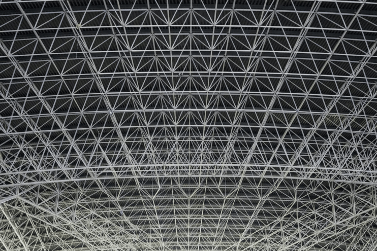
- Steel grid. Generally speaking, a grid is a spatial structure that is comprised of multiple rods connected to each other in a specific form. There are many grid types out there, and many different standards for them, as well. They are highly rigid and provide extensive seismic resistance, which makes them perfect for hangars, exhibition halls, gymnasiums, and so on.
- Steel building frame. Another popular structure type that is mostly used for various multi-story buildings is the steel building frame, which consists of columns and beams that form structures capable of withstanding both vertical and horizontal pressure. A common choice for high-rise buildings, commercial offices, conference buildings, and so on.
- Steel truss. The truss structure is made of multiple rods that are hinged at each end of a rod. It requires less steel than regular steel structures, weighs less, and can withstand more force – which is why it’s often used for bridges, roofs, tower corridors, TV towers, oil platforms, and so on.
Design of steel structures
As with any moderately sized structure of any material, a lot of calculations have to be done at the design stage so that the building in question won’t collapse under its own weight. When it comes to steel structures, there are two main approaches to steel structure design (sometimes called a design philosophy):
- Load and Resistance Factor Design (LRFD, also called Limit State Design – LSD);
- Allowable Strength Design (ASD).
From the design standpoint, there are specific conditions that can be theoretically applied to steel structures called limit states. The limit state represents a point, after which a component or an entire steel structure is no longer capable of performing the purpose it was created for.
There are many different examples of limit states that can damage the structure in some way, making it unavailable for future usage – and this also needs to be kept in mind as early as the design phase, aside from the overall cosmetical approach to structure design.

Some examples of limit states are cracking, torsion, fatigue, shear, flexure, buckling, and so on. To tackle all of these potential issues at once, there’s a specific approach to steel structure design that has been implemented called LRFD – Load and Resistance Factor Design.
It is a method of structural engineering that uses limit states to analyze potential issues and create structures that would be far more likely to sustain those issues for far longer than before. This method accounts for both resistance and variability in load, achieving fairly high levels of safety for the majority of limit states.
If the concept of LRFD seems far too complex for you – there is an alternative called ASD – Allowable Stress Design. It is a relatively simple approach to building safety and mostly bases its calculations on a linear elastic behavior of the material in question – in our case it’s steel. It is mostly based on experience with the material and involves only two big factors – the potential maximum load of a structure and a linear safety factor.
When it comes to a direct comparison between ASD and LRFD when it comes to the design of steel structures, ASD would be the simple but less accurate one, while LRFD remains more complex, but also more reliable in its calculations. Additionally, LRFD takes into account way more factors when calculating its design, such as different values for live loads and dead loads – which are not calculated differently at all when it comes to ASD.
Design methods for steel structures
There are three main design approaches to steel structure creation called simple, continuous, and semi-continuous, respectively. These designs showcase how various types of structures are created using several different design approaches, and not one single uniform design method.
Simple steel structure design
Simple approach to steel structure design is most likely the least complicated out of these three methods, and also the most popular by far. It uses an assumption that one connected member does not transfer any momentum to another member, with the only exception being nominal moments (joints’ eccentricity).
The provision of bracing is ensuring that the structure in question is resistant to both sway and lateral loads (concrete cores are also used for that in some cases). Since simple steel structure design assumes that all of the joints are perfect pins (for the sake of easier calculation across the board), the designer of the project should make sure that the connections within the project are detailed in such a way that allows no potentially negative moments to be developed in the first place.
This approach to design as a whole has proven itself effective for many years and thousands of projects, which is why it is highly recommended to refer to joints with standard connections in this type of steel structure design approach.
Continuous steel structure design
Unlike the previous example, continuous steel structure design assumes that joints are both rigid and capable of transferring momentum from the get-go. Additionally, beams and columns bending (frame action) are what ensures the stability of the frame as a whole when it comes to being influenced by sway.
Continuous design is much more reliant on software calculations when compared with simple design, especially when it comes to frame analysis operations. The main reason for that difference is the overall complexity of continuous structures as a whole, which is usually far higher than with simple structure design.
Additionally, this entire approach can be separated in two categories depending on which design method is used for the entire frame – plastic or elastic. These two are quite different from one another, and differences themselves can be quite drastic.
Plastic design, for example, puts the strength of the joint as the biggest factor that determines the overall load capacity of the structure – it greatly affects the collapse mechanism depending on whether plastic hinges are going to occur in the members or in the joints. If the latter is the case, the joint itself should accommodate the resulting rotations beforehand by providing sufficient ductility for the material. At the same time, the stiffness of the joint is important when it comes to calculations for other structure elements, such as sway stability, as well as sway and beam deflections.
Elastic design, on the other hand, implies that each joint must be able to carry quite a lot on its own – such as the force, the momentum, and the shears that may arise after the frame analysis process. Joints also have to have a sufficient level of rotational stiffness so that the difference between the real and the calculated force distribution is not too massive.
Semi-continuous steel structure design
Semi-continuous steel structure design approach is both the most complicated out of the three and the least represented when it comes to actual construction projects due to both its complexity and how recently it was introduced in the industry. One of the biggest reasons for the complexity of the semi-continuous design approach is that it implies calculating joint response much more accurately than with any other method.
This method is also the least suitable out of the three when it comes to more common and routine design choices since this kind of accuracy with connection behavior for joints is extremely difficult and resource-heavy, takes a lot of time, and requires the usage of very specific computer software.
This design method can also be split into two separate procedures that use different frame types – braced or unbraced. Unbraced frames are the ones that generate resistance via bending moments in either beams or columns. Braced frames, on the other hand, have a core or a bracing system of sorts that generates resistance to lateral loads.
Here is the overly simplified explanation of how both unbraced and braced frames work and what is different for them:
- Unbraced frames consider joints for columns or beams to be pinned when calculating gravity loads – but there is also an assumption of them being rigid when under wind loads, with frame action carrying lateral loads in these situations.
- Braced frames use the real join behavior to reduce deflections and also reduce the bending moments that are otherwise applied to the beams in full force;
How steel structures are designed – a guideline
Each and every design process as a whole is going to have its own unique parts and nuances, but we can safely say that there are at least 6 general steps in the process of designing a steel structure:
- Figure out if it is even possible to create this particular structure using steel. Steel as a material is not as universal as it may seem at first glance, and creating some structures from steel might not be the most effective way to approach construction. Steel is at its best when used for complicated frames with large spans and sizable heights – with some of the more notable examples being warehouses, hangars, factories, bridges, stadiums, and so on.
- The next step should also be rather obvious – to figure out both the layout and the structure type that is going to be produced. This choice is usually done in collaboration with professional engineers, since there are a lot of parameters that have to be taken into account here – to accommodate all kinds of potential issues, such as snow or rain being accumulated on the roof, as well as choosing the correct support frame, figuring out if the combination of steel and concrete would be more viable here, and so on.The general layout of the structure is also decided upon within this step, with uniform stiffness across the board, correct calculation of load distribution, the structure’s future parameters as a whole, and more. Moving and heavy loads should be easily transmittable to the foundation, anti-slide support should be equally distributed among all of the columns, etc. This step also covers the inclusion of secondary beams for a number of purposes, if necessary.
- Analyzing the structural integrity and other similar parameters is the next step for this process, and this one in particular is often used as a baseline for other, more detailed analysis processes. Depending on the structure type, it may be possible to acquire some of the parameters such as internal forces or deformation without the help of the analysis software – taken exclusively from mechanical manuals or other reference books.
- Engineering judgment should have a lot of influence on the overall design for any steel structure since it can be used to confirm or reject specific design choices as physically doable or unusable, respectively. Engineering decisions have to be taken into account in most cases if the software used for calculations was set up correctly beforehand. Any novice in the field should comply with these engineering decisions in the majority of use cases, and only more experienced designers may consider not using some of the engineering decisions.At the same time, these engineering judgments should not be taken at the expense of chosen concepts, conditions, or structure types – engineering (quantitative) computation has less importance than the notion of staying true to the original concept of the building. As such, overusing engineering software is not recommended and the most profitable course of action is to pay close attention to both engineering judgements and the conceptual design as a whole.
- Material selection is another notable step in this process since steel in itself is an alloy that can be modified in a multitude of different ways, which creates a plethora of different steel variations to choose from. Most projects use the same steel grade for the entirety of the primary project structure to simplify calculations and avoid potential problems down the line.Different alloys of steel have different use cases, strengths, and weaknesses – and there are even examples of software that can re-calculate a number of project parameters depending on the material chosen. There are even examples of software that allow its users to move “up” from the chosen material type if the previous one did not meet the specifications of the project. That way, it is possible to pick a number of similar steel alloys before finding the one that fits the project the most – this kind of software also tends to drastically decrease the amount of work architects have in this part of the project.
- The last, but not the least part of this process is the drawing preparation. The final design drawing consists of two completely different parts – the design sketch and the construction detail drawing. The former is provided by the design drawing company as a baseline for the project itself, while the latter is used as the baseline for the actual construction process, with material lists attached to it.The construction drawing itself usually takes the design drawing as the baseline, and it can take a number of parameters from the aforementioned design drawing to make the creation of a construction drawing that much easier. Design requirements, technical data, load data, and structural arrangements are only some of the information elements that can be utilized in the process of creating a construction drawing.The construction drawing itself is often referred to as a processing drawing or a stakeout drawing, and it should be accurate and detailed enough to serve as a guide for the following workshop/manufacturing processes, with a complete list of materials and other components that are necessary for the construction to be completed.
Design standards for steel structures
Since the steel structure design process as a whole deals with a lot of different models, standards, and methods, producing real-life structures of massive size, it is only natural for it to have actual government-regulated standards of how designs should be approached.
A good example of that is Eurocode – a set of 10 European standards that specify all kinds of rules and regulations about structural design within the borders of the European Union. As for the specific code that covers steel projects, it is EN 1993 Eurocode 3.
This Eurocode complies with the basic design principles of the European Union when it comes to various buildings and other projects that are designed with steel in mind. It covers fire resistance, serviceability, durability as well as regular resistance of the steel as a material for design purposes.
The scope of EN Eurocode 3 is bigger than any other Eurocode, mainly because of how many different types of structures and projects can be created using steel – covering topics such as welded joints, bolted joints, and structure slenderness. Other topics mentioned in EN 1993 are separated into parts based on the structure type, such as silos, towers, buildings, bridges, chimneys, tanks, and common rules, to name a few.
This Eurocode was created to be used in combination with other Eurocodes, such as EN 1990, EN 1991, EN 1090, and EN 1992 to EN 1999, depending on which parts of these Eurocodes are dealing with steel structures.
Conclusion
Levstal is capable of providing a lot of different types of steel structures, such as metal beams, cranes, bridges, quay constructions, shiploaders, ramps and even bearing structure elements. The company’s experience in working with steel is a guarantee of quality and variability.
Levstal’s services are used by clients from all over the world – from Germany, Sweden, and Belgium to Japan, North America, and the Netherlands, among others. Levstal offers support for the entire project’s lifecycle and personalizes the customer experience for each and every one of its clients.
- The definition of steel structure
- Benefits and disadvantages
- Detailed steel structure construction process
- Foundation
- Columns
- Beams
- Floor system
- Types of steel structures in the form of buildings
- Design of steel structures
- Design methods for steel structures
- Simple steel structure design
- Continuous steel structure design
- Semi-continuous steel structure design
- How steel structures are designed – a guideline
- Design standards for steel structures
- Conclusion


